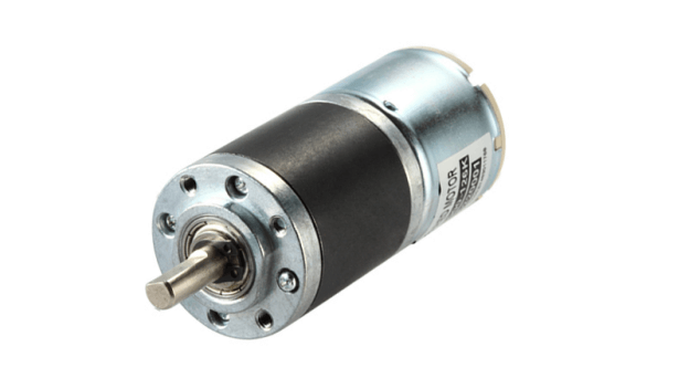
For you to understand what reduction gear motors are, it is crucial to start by understanding what gear motors are. Gear motors are made in a mechanism that enables them to adjusts the speed of electric motors, increasing or reducing it.
The mechanism is actually a series of gears making up a chain that works on a set of rotary parts. It is merely the motor, together with a reduction gear train. The gear train reduces the speed of the motor by increasing the torque. Gear ratios can vary between 3 and 500. The bigger the ratio, the more the gear reductions required; hence the more gears there shall be.
Gear reduction has the reverse effect on torque. In wind turbines, a slow turbine blade is converted to a high speed that can produce electricity by increasing speed and reducing torque. However, there are gear motors that work as reducers.
This is because the input gear has fewer teeth than the output gear, which increases torque while reducing the speed. Examples of reduction gear motors include the planetary speed reducer, worm drive, and parallel shaft gear motor.
The planetary speed reducer includes components such as the sun, planet carrier, and crown. The sun is a central gear that derives its name from the fact that it rotates on a central axis. Another component is the planet carrier. This one gears of the same sizes that are to merge with the sun.
The crown is the third component that using teeth on the inner side holds up the gears together. This kind of gear motor is used in applications that require a high level of accuracy. Examples include Industrial automation machines, vending machines, or robotics. The uniform transmission assures reliable movement as well as durability.
More teeth in the setup ensure that it can stand more torque. Another advantage of this motor is the cylindrical shape that makes it possible to install it anywhere.
The worm drive reduction gear motor, unlike the planetary reduction gear, offers speed reduction at a less number of steps. This one has a single shaft at its middle, surrounded by a toothed worm wheel. It has significantly less efficient than the planetary gear motor, which is a result of sliding contact that causes a lot of friction.
This also makes for quieter performance, making this setup the most suitable for use in units where noise should be minimized, for example, in lifts. They should, however, be used in applications that do not require high speed. Another suitable application is lifting and hauling of loads because they are self-locking.
Final Thoughts
In parallel shift gears, unlike in their worm drive counterpart, the motor shaft and speed reducer are parallel in placement. It is this design that makes them suitable for applications where space is a major concern. The types of gears they use include the spur gears, whose teeth are parallel to the driveshaft.
Parallel shift gears can also use helical gears, which are characterized by teeth that slant from the rotation axis. In some cases, they can use double-helical gears that are used in cranes, fluid pumps, and other transmission applications.


